Documentation for the excavator bucket
The excavator’s bucket has usually a complex shape that is not suitable for first-order modelling. In this simulator, the bucket is approximated as a triangular prism to simplify its representation. An illustration of the simulated bucket is provided below.
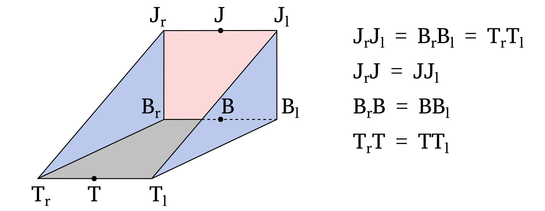
The different parts of the bucket are labeled as follows:
Jrepresents the bucket joint.Brepresents the bucket base.Trepresents the bucket teeth.The surface defined by the vertices \(T_lT_rB_rB_l\) is referred to as the bucket base.
The surface defined by the vertices \(J_lJ_rB_rB_l\) is referred to as the bucket back.
The surface defined by the vertices \(J_rB_rT_r\) is referred to as the bucket right side.
The surface defined by the vertices \(J_lB_lT_l\) is referred to as the bucket left side.
The surface defined by the vertices \(J_lJ_rT_rT_l\) is referred to as the bucket front. Note that it does not correspond to a bucket wall.
The reference pose of the bucket is specified when creating the Bucket class and is defined by the fields j_pos_init_, b_pos_init_, and t_pos_init_, which correspond to the positions of the bucket joint, base, and teeth, respectively.
The centre of rotation for the bucket is typically the bucket joint, but it can be a different point depending on the specific bucket design.
In that case, a different bucket origin (o_pos_init) can be provided when building Bucket.
The position of the bucket joint, base, and teeth are generally defined relative to the bucket origin.
The pose of the bucket (pos_) is provided to the simulator as the Cartesian position of the bucket origin and its orientation (ori_) relative to the reference pose, using the Quaternion notation.